Tuesday 7 January 2014

Electromagnetic Radiation ဘယ္လိုျဖစ္လာတာလဲ?

English လိုကေတာ့ "All radiation is caused by accelerating charges which produce changing electric fields. And due to Maxwell's Equations, changing electric fields give rise to changing magnetic fields and hence we have electromagnetic radiation".

ဖတ္ၾကည့္ရင္ေတာ့ နားလည္သလိုပဲ။ ထဲထဲဝင္ဝင္လိုက္ေမးၾကည့္ရင္ ေသခ်ာေျဖႏိုင္တဲ့သူက အေတာ္ကို ရွားတာသြားေတြ႕ရတယ္။

ဥပမာေလးနဲ႕ ရွင္းရေအာင္...

ေရပိုက္ေခါင္းထဲကေန ေရဘယ္လို ထြက္လာလဲ ၾကည့္ရေအာင္။ ေရက သူဟာသူ ေရပိုက္ထဲမွ စီးဆင္းေနရင္ Constant velocity နဲ႕သြားေနတယ္။ ေရပိုက္အဝလည္းေရာက္ေရာ ျဖာထြက္သြားတယ္။ wave ပံုစံျဖာတြက္သြားတယ္။ ေရပိုက္ အဝရဲ႕ ပံုစံကို မူတည္ၿပီး ျဖာထြက္တဲ့ ပံုစံ ကြာသြားႏိုင္တယ္။ အိမ္မွာ ကိုယ္တိုင္ ကိုယ္က်စမ္းသပ္ႏိုင္ပါတယ္။

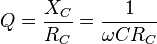
Electron ေတြရဲ႕ စီးဆင္းပံုကလည္း အတူတူပါပဲ။ Rate of change of velocity (Acceleration) ျဖစ္ေစတဲ့ အရာေတြမွာ စီးဆင္းမယ္ဆိုရင္ RF Radiation ျဖစ္မွာပါပဲ။ အကယ္၍မ်ား PCB ကို 90 deg Trace ဆြဲခဲ့မယ္ဆိုရင္ Radiation ျဖစ္မွာပါ။ Antenna ရဲ႕ အလုပ္လုပ္ပံုကလဲ အတူတူပါပဲ။ Electron က Transmission Line ျဖတ္ Antenna ကို ေတြ႕ေတာ့ ဆက္သြားစရာဆိုေတာ့ Air Medium ပဲရွိတယ္။ ဒီေတာ့ Electron ေတြျဖာထြက္တဲ့ အခါ Electric Field ကို ျဖစ္ေပၚေစတယ္။ Electric Field (E) ရွိရင္ Magnetic Field က automatic ျဖစ္ေပၚေစတယ္။ ေနာက္ဆံုး Electromagnetic Wave ကို ျဖစ္ေစျပီးေတာ့ Radiation Frequency လို႕ ေခၚတြင္ေစတယ္။

ဒီေလာက္ဆို RF ဆိုတာ ဘာလဲ သိေလာက္ၿပီ ထင္ပါတယ္။

ေနာက္ဆံုး ေမးခြန္းေလး တစ္ခုေမးထားခဲ့မယ္။

50 Hz ရွိတဲ့ AC 230V ဟာ ဝါယာႀကိဳးထဲမွာ ျဖတ္သန္းစီးဆင္းတဲ့ အခါ Radiation ျဖစ္ႏိုင္ပါသလား?

မျဖစ္ဘူးဆိုရင္ ဘာေၾကာင့္ မျဖစ္တာလဲ?

ဘယ္လို အေျခအေနမ်ိဳးေရာက္ရင္ Radiation ျဖစ္မွာလဲ။

PS: Electronics က တစ္ခုနဲ႕ တစ္ခု ဆက္စပ္ေနေလေတာ့ RF Circuit Design မွာ Analog & Digital Circuit အေၾကာင္းမစဥ္းစားခ်င္လို႕မရပါဘူး။ Vice Versa...

သီဟေက်ာ္
Special Diploma in Wireless Technology
M.Sc(Computer Control & Automation)
B.Eng(Electronics)

Monday 11 November 2013

Reduction of Common Mode (CM) and Differential Mode (DM) radiated emission

 Differential Mode Radiation can be reduced by

1) Reducing the magnitude of the current
2) Reducing the frequency of harmonic content of the current
3) Reducing the loop area

Common Mode Radiation can be reduced by

1) Minimising the source voltage that drives the antenna (normally ground potential)
2) Providing a large common mode impedance in series with the cable or printed track
3) Shunting the current to ground
4) Shielding

Reduction of Common Mode (CM) and Differential Mode (DM) radiated emission

To reduce the radiated emission, we must;
1) Reduce the frequency of the signal, ie, the rise and fall time, if possible
2) Reduce the loop area – eliminate or reduce all loop area by reducing the ground loop, the signal loop by decoupling
3) Reduce the inductance of the ground plane, mutual inductance of signal and return paths. By minimising the loop area where the signal flows, we have to reduce the mutual inductance in that circuit.
4) Eliminate or reduce all radiating antenna
5) Reduce or eliminate the noise source, differential voltage, if possible. Etc.

Methods of reducing of susceptibility to radiation

1) Balance the circuit, if possible
2) Reduce all loops that can pick up the radiation by induction current flow
3) Increase/decrease the impedance of the circuit to pick up depending on whether it is near field magnetic or electric field induction.
4) Reduce or eliminate all pick up antennas
5) Apply shield and crosstalk reduction technique, etc.

Tuesday 29 October 2013

EMC Consideration

Overview Of EMC

Electromagnetic interference is a serious and increasing form of environmental pollution. The large number of electronic devices in common use is partly responsible for this trend. Adopting the practices of electromagnetic compatibility (EMC) controls the pollution level of electromagnetic interference.
Definitions
  Electromagnetic Compatibility (EMC):
Ability of a product, equipment, system to operate satisfactorily in, and not overly contribute to, an electromagnetic environment.
Electromagnetic Interference (EMI):
Electromagnetic energy emanating from one device which causes another device to have degraded performance.
Electromagnetic Susceptibility (Immunity) (EMS):
Ability to function properly in its intended electromagnetic environment. Tolerance in the presence of electromagnetic energy.
Simply put, EMC is to design equipment that  neither generates, nor is susceptible to, interference.

The performance level and requirement of Electromagnetic Compatibility (EMC) for any electronic product or system are specified by EMC regulations. These specified levels are enforced by individual country’s EMC regulations and standards. Failing to comply with these requirements can result in forced removal of a product from the marketplace, confiscation of non-compliant product, monetary fines, and in extreme cases, imprisonment.
Countries adopt different EMC Standards. Most adopt CISPR (International Special Committee for Radio Interference) as their national EMC regulation. In the US, the body responsible for EMC is FCC (Federal Communications Commission). For military applications, the EMC standard is MIL-STD-461E. These EMC Standards specifies what facilities to be used and how measurement are to be carried out.

Saturday 21 September 2013

Filter Design Basics

  1. Center Frequency, Fo
  2. Stopband Cutoff Frequency, Fs
  3. Selectivity Factor, Q
  4. Shape Factor, SF
  5. Insertion Loss
  6. VSWR and Return Loss
  7. Phase Linearity and Group Delay
  8. Filter Impedance

 Types of Filters


The two classical approaches in the design of filters are
  • Image-parameter
  • Network method

Image-parameter method 

        - treats the filter as a transmission line and uses lumped components.
  • Constant k filter
  • m-derived filter - is a modification of the constant k filter in order to vary the impedance (constant) and the shape factor (steeper).

Network method

     - based on frequency response curve or transfer function.

Other common filter design methods are
  • Top-coupled resonator
  • Varactor-tuned BPF (Band Pass Filter)

Thursday 22 August 2013

How to choose CAPACITOR and INDUCTOR for High Frequency Application

Capacitor

At RF, a capacitor may be modelled as shown below;

where:
            C = capacitance
            ESR=equivalent series resistance due to heat dissipation loss expressed either as power factor or dissipation factor
            ESL= some parasitic inductance (ESL) due to electrodes

Losses in capacitor may be expressed as capacitor Q which is defined as;


According to above figure, capacitor works as a capacitor before self-resonant frequency.
Capacitor will not work as a function of capacitor after self-resonant frequency and it behave as an Inductor.

Therefore the capacitor should be chose as per below criteria.

Freq (srf) >> Freq(rf)
where:
            Freq(srf) = self-resonant frequency
            Freq(rf) = the radio frequency used in design

Inductor

At RF, an inductor may be modelled as shown below;


Monday 8 July 2013

RF Basics

Frequency

Frequency ဆိုတာ RF(Radio Frequency) တစ္ခုလံုးရဲ႕ အေျခခံအက်ဆံုး အစိတ္အပိုင္းျဖစ္တယ္။ Microwave Theory ပိုင္းမွာလည္း Frequency တန္းဖိုးက အေရၾကီးျပီး ရွဳပ္ေထြးလြန္းတဲ့ တြက္ခ်က္မွဳေတြမွာ အျမဲေနရာယူေနတာပါ။ Frequency ဆိုတာနဲ႕ sin wave နဲ႕ cosine wave ေတြကို သတိရၾကမယ္ထင္ပါတယ္။

Electromagnetic (EM) Wave


Electronic Wave အေၾကာင္းေျပာၿပီးဆို Magnetic Wave က ေနာက္က ဆက္ပါလာတာပါ။ Electronic wave သည္ Magnetic wave ႏွင့္ ေထာ့င္မွန္က် သည္။ ေအာက္ကပံုကေတာ့ sine wave ကို EM wave အေနနဲ႕ ျပထားတာပါ။


Radiation Pattern


Radiation Pattern ဆိုတာ Antenna ကေန ထုတ္လြတ္လိုက္တဲ့ Power ကို ေဖာ္ျပသည္လို႕ အဓိပၸါယ္ မွတ္ယူႏိုင္သည္။ Radiation Pattern ရဲ႕ ပံုက ပန္းသီးတစ္လံုးရဲ႕ပံုနဲ႕ တူတယ္။ အလယ္ဝင္ရိုးကို EM Wave လံုးဝမလြတ္ထုတ္ႏိုင္တဲ့ Null Location လို႕ေခၚျပီး အဲဒီ Null မ်ဥ္းေပၚမွာရွိတဲ့ ဘယ္ Receiver မဆို Transmitter က လြတ္တဲ့ သတင္းအခ်က္အလက္ေတြကို ရရွိမည္မဟုတ္။

Field Regions

Field Regions ၃ ခုရွိတယ္။
  1. Far Field (Fraunhofer) Region
  2. Reactive Near Field Region
  3. Radiating Near Field (Fresnel) Region

Far Field (Fraunhofer) Region

Far Field Region က အေရးအၾကီးဆံုးျဖစ္သည္။ Antenna ရဲ႕ Radiation Pattern ကို Far Field Region နဲ႕ပဲ အဓိပၸါယ္ဖြင့္ဆိုသည္။ Antenna အလုပ္လုပ္တဲ့ Region လို႕ သတ္မွတ္လို႕ရပါသည္။ Far Field Region ျဖစ္ဖို႕ အခ်က္ ၃ ခ်က္နဲ႕ ျပည့္စံုရပါမယ္။
where; R = Far Field Region, D = Dimension of antenna

">>" ဆိုတာ အရမ္းၾကီးရမယ္လို႕ အဓိပၸါယ္ရတယ္။ အနည္းဆံုး ၁ဝ ဆၾကီးရပါမယ္။

Reactive Near Field Region 

Reactive Near Field Region ဆိုတာက Antenna ပါတ္ဝန္းက်င္က ေနရာေတြကို ဆိုလိုသည္။ Near Field Region ကို ေအာက္ပါအတိုင္းတြက္ခ်က္ႏိုင္သည္။

Radiating Near Field (Fresnel) Region

Radiation Near Field Region ကေတာ့ Far Field (Fraunhofer) Region နဲ႕ Reactive Near Field Region ၾကားမွာ ရွိပါသည္။ Radiation Near Field Region ကို ေအာက္ပါအတိုင္းတြက္ခ်က္ႏိုင္သည္။


Sunday 7 July 2013

Digital Transmitter Measurement

Objective

To understand
  1. Characterization of IQ modulator: the Carrier Leakage and Sideband Suppression
  2. The 1dB-Compression Point of a Transmitter. 
  3. The output 3rd Order Intercept Point (OIP3) of a transmitter.
  4. Modulation Analysis: Channel Power, ACPR,EVM

Characterization of IQ modulator: the Carrier Leakage and Sideband Suppression

A common approach to characterize the I-Q modulator performance is to apply two signals V sin(wt) and Vcos(wt) to the I and Q input terminals and examine the spectrum produced at the RF output.  In the ideal case, the output in the band of interest is simply given by;


  • In practice, there are imbalances in the device (For example, gain and phase imbalance in the mixers and phase shifter network).


  • Carrier leakage in a function of DC offset.
  • It can be shown that the sideband suppression is a function of G & Φ.

1dB Compression Point

  • The point at which the output power differs from the ideal transfer function by 1dB as the input power increases.

Dynamic Range

  • The input power range over which the receiver provides a useful output. The low power limit is the sensitivity specification and upper limit is the input power at 1dB compression point.

Dynamic Range = Input 1dB Compression Point - Sensitivity Level


Output 3rd Order Intercept Point (OIP3)


IP3 can be calculated without extrapolation using above formula.

Modulation Analysis: Channel Power, ACPR, EVM, CCDF

Channel Power: Channel power is the average power in the frequency bandwidth of the signal of interest.  The measurement is generally defined as power integrated over the frequency band of interest.


ACPR: The adjacent Channel Power Ratio (ACPR) is usually defined as the ratio of the average power in the adjacent frequency channel to the average power in the transmitted channel.

EVM: The error vector is the vector difference at a given time between the ideal reference signal and the measured signal.  The error vector is a complex quantity that contains a magnitude and a phase component.  Error Vector Magnitude (EVM) is the root-mean-square (RMS) value of the error vector over time at the instants of the symbol clock transitions.

CCDF: The CCDF curve shows the probability that the power is equal to or above a certain peak-to-average ratio.  Figure A shows the power versus time plot.  This plot represents the instantaneous envelope power of the waveform.  Figure B displays the CCDF curve of the signal.  Here the x-axis is scaled to dB above the average signal power, which means we are actually measuring the peak-to-average ratios as opposed to absolute power levels.  The y-axis is the percent of time the signal spends at or above the power level specified by the x-axis.  For example, at t=1% on the y-axis, the corresponding peak-to-average ratio is 7.5dB onthe x-axis.

To be continued....

Saturday 6 July 2013

Virtual Router - Wifi Hot Spot for Windows 8, Windows 7 and 2008 R2

Virtual Router turns any Windows 7, Windows 8 or 2008 R2 computer into a Wifi Hot Spot using Windows' Wireless Hosted Network (Virtual Wifi) technology.

Where can Virtual Router be used?

Anywhere you are!
  • Home
  • Office
  • School
  • Airport
  • Bus Station
  • The Park
  • Grandmas House
  • The In-Laws
  • Absolutely Anywhere!


Friday 5 July 2013

Explain how the length of the antennas, the transmit power and receiver sensitivity can have an impact on your CPE wireless coverage?

Antenna

The length of antenna is defined by the wavelength of the frequency. The longer length of antenna, the higher the gain of the antenna in dBi and the better coverage of CPE.

Transmit Power

Transmit Power is an important parameter of wireless design.
The higher transmit power at lower EVM can give a better performance and longer range of wireless coverage.

Sensitivity


Received Sensitivity is to measure the minimum received signal level of CPE.
Greater sensitivity = longer range

As the signal propagates away from the transmitter, the power density of the signal decreases, making it more difficult for a receiver to detect the signal as the distance increases. Improving the sensitivity on the receiver (making it more negative) will allow the radio to detect weaker signals, and can dramatically increase the transmission range.